Basics of Your Home's Electrical System
If you are looking for more information on the subject matter covered here, many resources are available on the resources page for download:
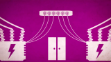
Transmission of Electric Energy:
Electricity is transferred from power stations to consumers over long distances through the wires and cables of the power companies. When a current flows through a wire, a bit of energy is lost in the form of heat. The higher the current, the more energy is lost. To reduce these losses, the power companies transmit electricity at a low current, but this requires a high voltage.
Step-up transformers are used at power stations to produce the very high voltages needed to transmit electricity through the power lines. When the electric energy reaches the consumer area, it is transformed, which means changed, to a lower and safer voltage. Step-down transformers are used locally in sub-stations to reduce the voltage to safe levels.
Step-up Transformer
Transmission Lines
Step-down Transformer
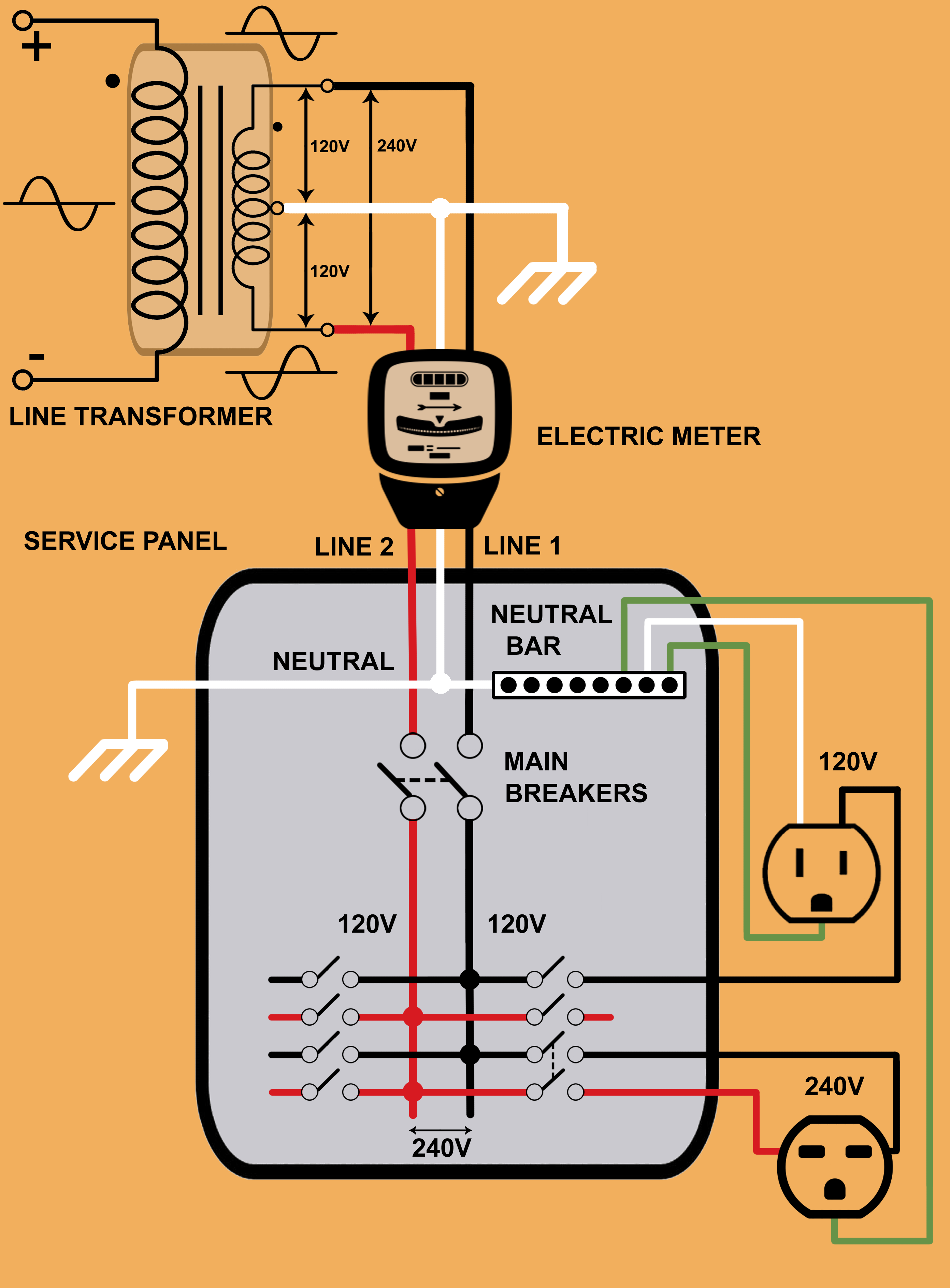
Now, let’s briefly review how electricity gets to your house. Most residential and light commercial homes in north America have a single-phase 3-wire 120V/240V service. It consists of two inverted relative to each other lines and a grounded neutral. Connecting an electric load between any line and the neutral yields 120 volts AC. Connecting between both lines yields 240 volts AC (see the diagram). The two 120V buses are derived from a step-down distribution transformer, which is usually mounted on a pole. Its secondary winding has a grounded center tap connected to neutral wire. The two end terminals are electrically "hot" with respect to the neutral. Note that both lines are derived from the same utility phase. That’s why such configuration is often called "split phase". The three conductors go from the pole to your electric meter. From the meter they run to the panel containing the main service disconnect. From there the lines go to magnetic circuit breakers that protect individual branches or circuits.
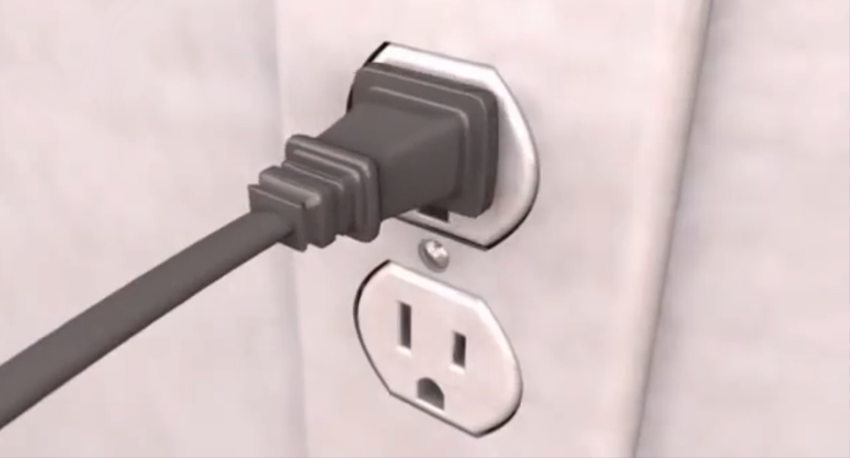
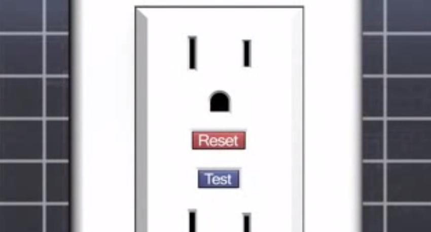
Why, you may ask, do we need a 3-wire configuration? Would not a single 120V bus be enough? The case is, a standard wall outlet is rated to 15A. Hence, the maximum power you can draw from such an outlet is 15×120=1800 volt-amps. Moreover, for continuous loads, NEC® recommends to limits the current on receptacles to 80%. Therefore, steady state current should be less than 12A (which corresponds to 120×12=1440 VA).
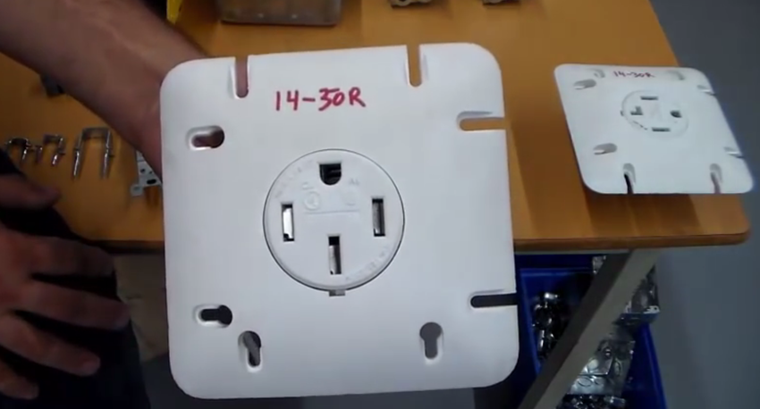
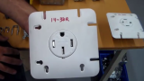
What if your appliance consumes more power? Large appliances such as a central a/c or driers are usually designed to work from 240V. This is done in order to reduce energy losses in the cables. When you double the voltage, you need half the current to deliver the same wattage and for lower currents you can use lower conductor thickness. That’s the main reason we are getting 240V. As you can see from this wiring diagram, it is obtained from two 120VAC lines, so we have two voltage levels.
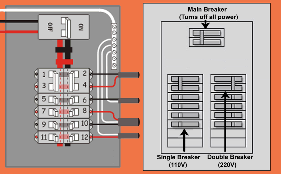
What's a circuit? What's an overload?
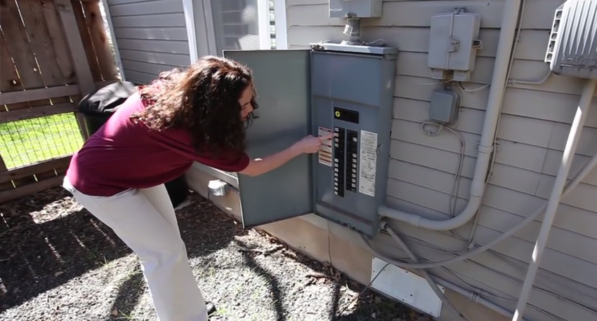
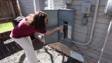
When electricity enters your home, it goes to a circuit breaker box (or fuse box in older homes), where it's divided into a number of circuits. Each circuit is protected by a breaker or fuse. Bedrooms, living rooms and family rooms where only lights, alarm clocks and other small electrical items are usually used are normally on 15-amp circuits. Kitchens, laundry rooms, bathrooms and dining rooms places where you're more likely to use toasters, irons, hair dryers and other big-watt items are usually served by heavier-duty, 20-amp circuits. Major appliances like 5,000-watt electric water heaters and 10,000-watt electric ranges demand so much electricity that they take their own 30 to 50 amp dedicated circuit, protected by big, "double pole" breakers.
The circuit breaker, the wire and even the wire insulation are all designed to work as a system and that system has limits. If you try to push more current through a circuit than it's designed then the circuit breaker senses the excess current and "trips" to stop the flow of power before damage occurs.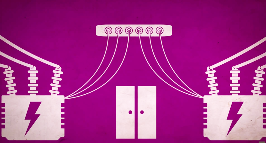
More training resources
See all